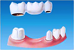
The crown restorations can be used to rebuild a single tooth or as a retainer for a fixed prosthesis.
Principles of tooth preparation
A good preparation ensures that subsequent techniques (e.g., interim restoration, impression making, pouring of dies and casts, waxing) can be accomplished.
The design and preparation of a tooth for a cast metal or porcelain restoration are governed by five principles:
A) Preservation of tooth structure
B) Retention and resistance form
C) Structural durability of the restoration
D) Marginal integrity
E) Preservation of the periodontium
Successful tooth preparation and subsequent restoration depend on simultaneous consideration of all these factors. Improvement in one area often adversely affects and may lead to failure in another area.
Communication between the clinician and dental laboratory regarding any deviation from “ideal” criteria is essential and can prevent misunderstanding, frustration, and ultimate failure.
A) Preservation of tooth structure
Excessive removal of tooth structure can have many ill effects. If a tooth is over-tapered or shortened too much, there will be an unnecessary sacrifice of retention and resistance.
Preservation of tooth structure

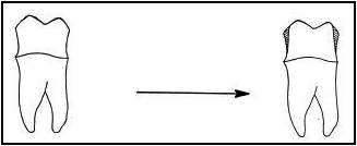
Tooth structure removed following minimal recommended dimensions.
- Anatomically prepared occlusal surface results in adequate clearance without excessive tooth reduction.
- A flat occlusal preparation will result in either insufficient clearance (1) or an excessive amount of reduction (2).
Anatomic occlusal reduction is conservative of tooth structure and gives rigidity to the restoration.

B) Retention and Resistance
The feature of a tooth preparation that resists dislodgement of a crown in a vertical direction or along the path of placement is known as retention.
The features of a tooth preparation that enhance the stability of a restoration and resist dislodgement along an axis other than the path of placement is known as resistance.
Retention and resistance form
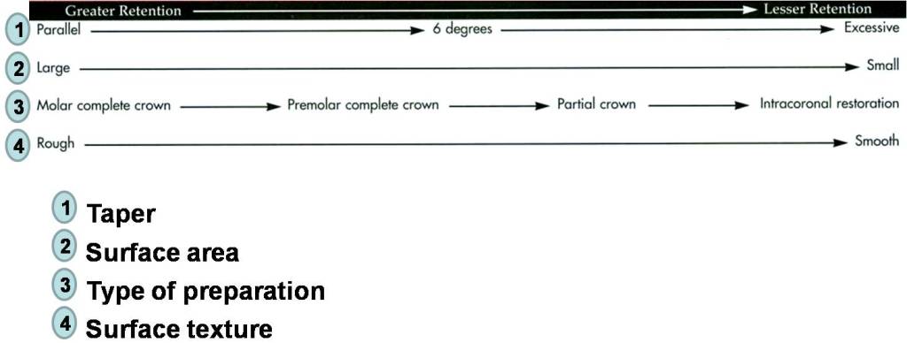
- Taper of about 6º between opposing walls (No undercuts or over reduction).
- Surface area of the occlusal surface.
- Length of the axial walls.
Factors influencing the retention of a cemented restoration:
Factors influencing the resistance of a cemented restoration:
Higher resistance Lower resistance

Taper
Theoretically, maximum retention is obtained if a tooth preparation has parallel walls. However, it is impossible to prepare a tooth this way; slight undercuts are created that prevent the restoration from seating.
“An undercut is defined as a divergence between opposing axial walls in a cervical-occlusal direction”.
A slight convergence, or taper, is necessary in the completed preparation. Too large will no longer be retentive.
Degree of convergence (taper) is recommended to be 6-degree.
C) Structural Durability
The casting must be rigid enough not to flex and break.
Sufficient tooth structure must be removed to create space for an adequate bulk of restorative material to accomplish this.
Structural durability
- Adequate occlusal reduction to allow bulk of metal.
- Functional cusp bevel to allow for adequate thickness of metal.
- Sufficient axial reduction.
- Rounded angles.
Occlusal reduction
Enough tooth reduction must be removed from the occlusal surface of the preparation, so that metal will be thick enough to prevent wearing or distorting.
A flat occlusal surface is undesirable, because metal in the area of the grooves will be too thin, with a risk of perforation.

Functional cusp bevel
A wide bevel should be placed on the functional cusps of posterior teeth to provide structural durability on this critical area.
Failure to place functional cusp bevel can result in thin, weak areas in the restoration.

Proper articulation of opposing casts is the responsibility of the dentist. This is particularly critical as the complexity of treatment increases.

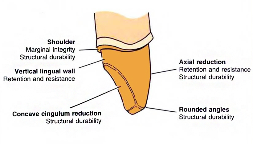
D) Marginal Integrity
Finishing line: is the junction between a cemented restoration and the tooth.

The more accurately the restoration is adapted to the tooth, the lesser is the chance of failure.
Margins should be easily discernible and accessible on the casts submitted to the technician. The saying “If you can’t see it, you can’t wax it” describes the situation well.

Marginal integrity
- Finishing line is clear, smooth and continuous.

Feather-edge and chisel finishing lines: are more conservative to tooth structure, but they are not recommended because they do not provide sufficient bulk and the location of the margin is difficult to locate.
Chamfer finishing line: has distinct margin, adequate bulk. It is used in full metal crowns, lingual margin (if unveneered) of ceramo-metal crowns.
Shoulder finishing line: provides bulk of restorative material. It is used in facial margin (veneered) of ceramo-metal crowns, and all-ceramic crowns.
The features of a tooth preparation a and the function served by each

Problems with Teeth Preparations
Problem 1: Under-reduced occlusal surface -> crown will be too thin

WHAT TO DO? : Further occlusal reduction
Problem 2: undercut within one surface

WHAT TO DO? : Further reduction of wall
Problem 3: Opposing walls diverge (Undercut)
WHAT TO DO? : Taper walls more
Problem 4: Finish line too light; walls are under-reduced

WHAT TO DO? :increase reduction
Problem 5: Finish line not continuous -> Inadequate reduction where proximal and buccal/lingual surfaces meet
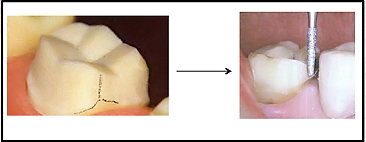
WHAT TO DO? : Finish line is placed
Other Troubleshootings on Tooth Preparation


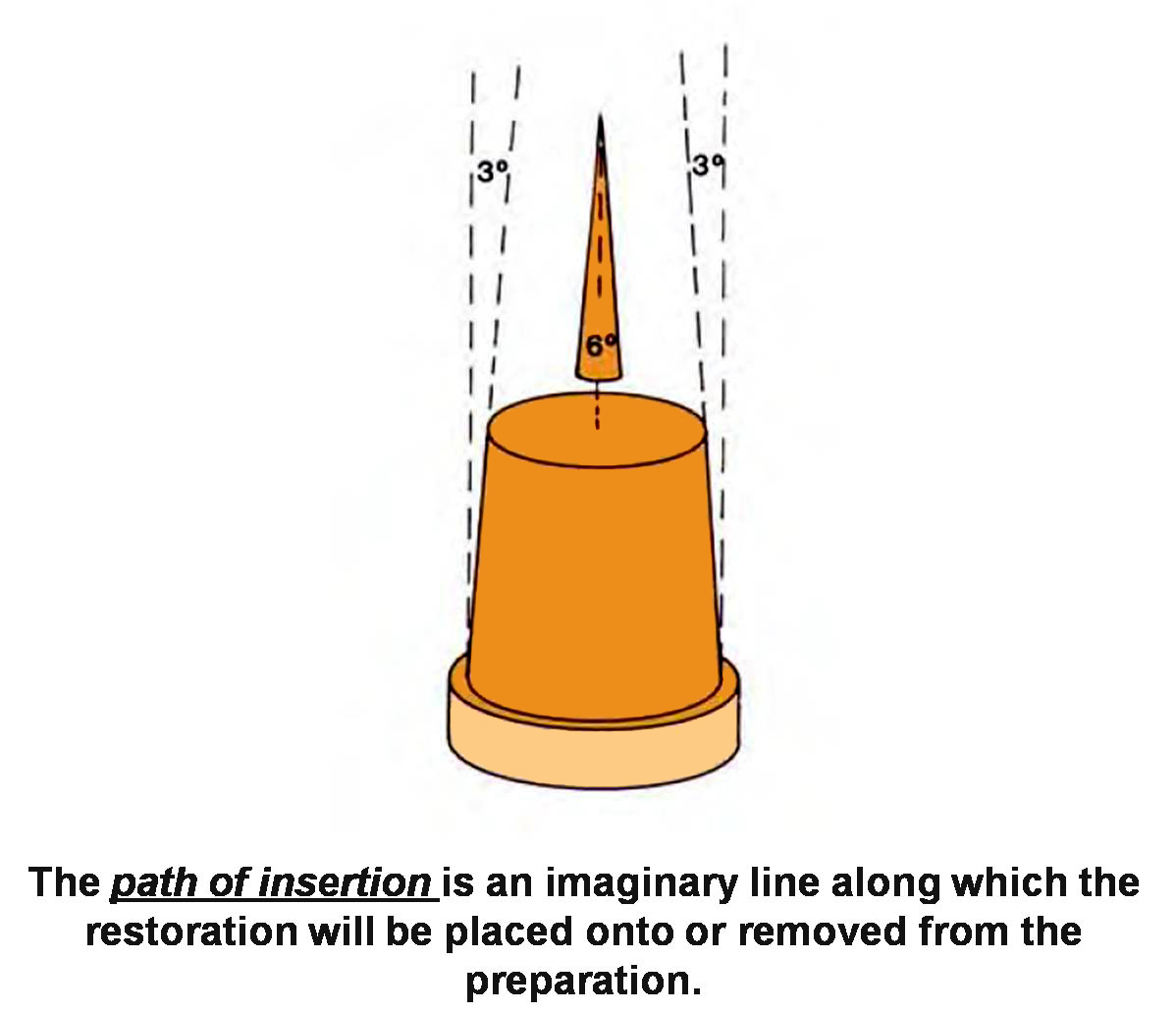

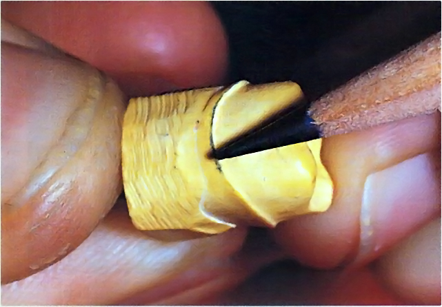
The recommended convergence angle is 6 degrees. This is a very slight taper. The angle between the hands of a clock showing 12:01 is 5 ½ degrees.


Example of how a clinician checks the tooth with a mirror.
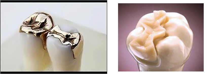
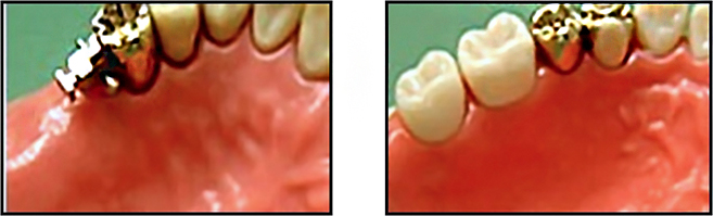
Complete Cast Crowns

The full-metal complete cast crown should always be offered to patients requiring restoration for badly damaged posterior teeth, although esthetic factors may limit its application.
The complete cast crown can be used to rebuild a single tooth or as a retainer for a fixed prosthesis.
It has the best longevity of all fixed restorations.

- The features of a preparation for a complete cast crown and the function served by each
Criteria for tooth reduction
The occlusal reduction must allow adequate room for the restorative material from which the cast crown is to be fabricated.
Minimum recommended clearance is 1 mm on nonfunctional cusps and 1.5 mm on functional cusps.
The Functional Cusps: The Lingual Upper and The Buccal Lower
Non-Functional Cusps: The Buccal Upper and The Lingual Lower (BULL)

- Recommended dimensions for a complete cast crown.
The occlusal reduction should follow normal anatomic contours to remain as conservative of tooth structure as possible. Anatomic occlusal reduction is conservative of tooth structure and gives rigidity to the restoration.
Proper placement of the functional cusp bevel achieves optimum restoration contour with maximum durability and conservation of tooth structure.
The functional cusp bevel is prepared by slanting the bur at a flatter angle than the cuspal angulation.
On most teeth, the functional cusp bevel is placed at about 45 degrees to the long axis.

Axial reduction should be parallel to the long axis of the tooth but allow for the recommended 6-degree taper or convergence, which is the angle measured between opposing axial surfaces.

The amount of axial reduction recommended is about 1 mm while following the contours of the tooth (occlusal 2/3), and about 0 .5 mm (gingival 1/3) to produce a chamfer finish line.
The margin should have a chamfer configuration and is ideally located supragingivally.
The chamfer should be smooth and distinct and allow for approximately 0.5 mm of metal thickness at the margin.
Retention form of an excessively tapered preparation can be increased by adding grooves, because these will limit the paths of withdrawal.

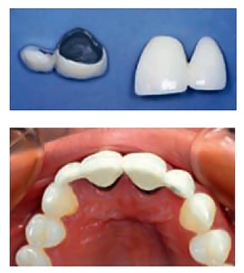
Metal-ceramic Crowns (PFM)
The metal-ceramic restoration, also called a porcelain-fused-to-metal (PFM) restoration, such a restoration combines the strength and accurate fit of a cast metal crown with the cosmetic effect of a ceramic crown.
With a metal substructure, metal-ceramic restorations have greater strength than restorations made of the ceramic alone.
To be successful, a metal-ceramic crown preparation requires more tooth reduction wherever the metal substructure is to be veneered with dental porcelain.
The metal should be 0.3 to 0.5 mm thick if it is a noble metal alloy, while a metal coping made of the more rigid base metal alloys can be thinner to 0.2 mm.

The metal coping in a metal-ceramic restoration is covered with two or three layers of porcelain:
1. Opaque porcelain conceals the metal underneath, initiates the development of the shade, and plays an important role in the development of the bond between the ceramic and the metal.
2. Body porcelain, or dentin, makes up the bulk of the restoration, providing most of the color or shade.
3. Incisal porcelain, or enamel, imparts translucency to the restoration.
Without the space for a sufficient thickness of ceramic material, two things can happen:
(1) The restoration will poorly contours, adversely affecting both the cosmetic effect of the crown and the health of the surrounding gingiva, and
(2) The shade and translucency of the restoration will not match adjacent natural teeth.
Recommended minimum dimensions for a metal-ceramic restoration:


Anterior metal-ceramic crowns preparation
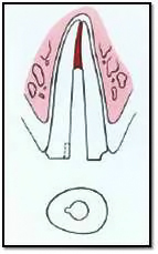
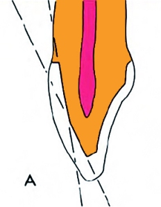 The labial reduction is carried out in two planes: the gingival portion to parallel the long axis of the tooth, the incisal portion to follow the normal facial contour.
Reduction in one plane parallel with the cervical plane may result in insufficient space of porcelain in the incisal half and an over-contoured restoration.
One-plane reduction may come dangerously close to the pulp.


Reduce the lingual concavity of the lingual surface with wheel-shaped or football-shaped diamond to provide adequate clearance for the restorative material.
Typically, 1 mm is required if the centric contacts in the completed restoration are to be located on metal. When contact is on porcelain, additional reduction will be necessary.

Axial Reduction of the Proximal Surfaces
Reduce the proximal surfaces with the diamond held parallel to the intended path of withdrawal of the restoration.
These walls should converge slightly from cervical to incisal/occlusal.
A taper of approximately 6 degrees is recommended.
A long-needle diamond is used to remove the contact area.

The finishing line must be smooth and continuous with other surfaces.

Rounding of any sharp angles on the incisal edges and all around the prepared tooth.

All-ceramic Crowns
All-ceramic crowns are some of the most esthetically pleasing restorations.
Because there is no metal to block light transmission, they can resemble natural tooth structure better in terms of color and translucency than any other restorative option.

The preparation sequence for a ceramic crown is similar to that for a metal-ceramic crown; the principal difference is the need for a 1-mm-wide finishing line circumferentially.
To prevent stress concentrations in the ceramic, all internal line angles should be rounded. The shoulder should be as smooth as possible to facilitate the technical aspects of fabrication.

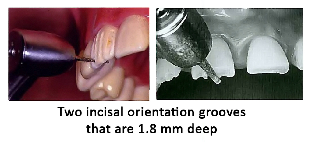
Incisal (Occlusal) Reduction
The completed reduction of the incisal edge should provide 1.5 to 2 mm of clearance.
This will permit fabrication of a cosmetically pleasing restoration with adequate strength.
- If the restoration is used for posterior teeth (rare), 1.5 to 2 mm of clearance is needed on all cusps.
Partial Veneers Crowns
An extra-coronal or intra-coronal metal restoration that covers only part of the clinical crown with preservation of one or more tooth surface.
Can be used as a single tooth restoration or as a retainer for FPD on both anterior and posterior teeth.
Types of partial veneers
For Posterior teeth :
- Three quarter crown.
- Seven eighths crown.
- MOD onlay.
For Anterior teeth :
- Anterior three quarter crown.
- Pin ledge crown.


Proximal Grooves
- Function: Retention, Resistance, and structural durability.
- Direction: Both grooves should be parallel to each other and parallel to path of withdrawal.
- Length: should extend to the full length of the proximal surface.

Occlusal Offset
- It is formed on the lingual incline of the buccal cusp to join the two proximal grooves (0.5 mm deep).

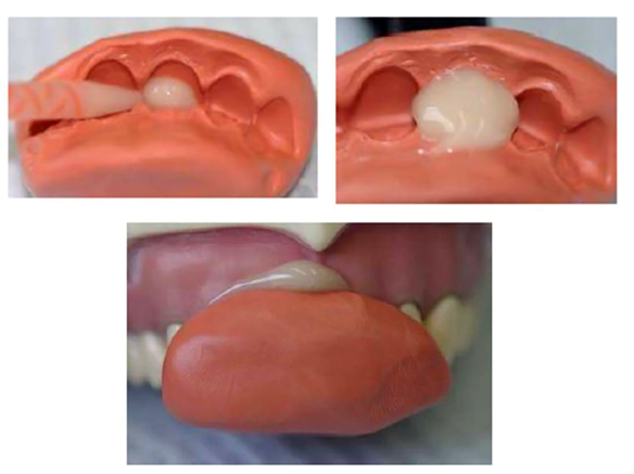
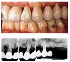
Post-and-core Restorations
Definition:
A post and core is a dental restoration for an endodontically treated tooth used to sufficiently build-up tooth structure for future restoration with a crown when there is no enough tooth structure to properly retain the crown.
Post and cores are therefore referred to as foundation restorations.

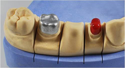
Cast post-and-core:
A one-piece foundation restoration for an endodontically treated tooth that comprises a post within the root canal and a core replacing missing coronal structure to form the tooth preparation.
One-piece post crowns
Where the post, core and final crown are constructed as one piece and are firmly attached to each other.
The crown could be all-metal or a metal with aesthetic facing.

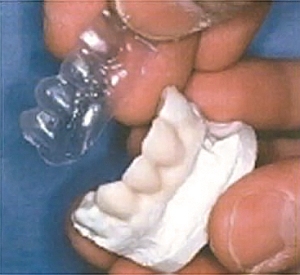
Two-piece Restorations
Where the post and the core are constructed and cemented as one piece, then the crown is constructed and cemented as the second piece.


Superior results can now be obtained with a two step technique consisting of a post-and core foundation and a separate crown (instead of one-piece post-crowns).
With the two-step approach of fabricating a separate crown over a cast post-and-core, achieving a satisfactory marginal fit is easier because the expansion rate of the two castings can be controlled individually.
The two-step approach further permits replacement of the crown, if necessary, without the need for post removal.
Be sure there is a positive stop for the post/core so that the casting does not act as a wedge (which may split the tooth).
This may be a flat area (90 degrees relative to the path of draw) or a slight contrabevel around the perimeter of the preparation.

Rotation of the post must be prevented by preparing a flat surface parallel to the post.
If insufficient tooth structure for this feature remains, an antirotation groove should be placed in the canal.
Rotational resistance can be obtained by preparing a small groove in the root canal. This must be in the path of placement of the post-and-core.


– end –


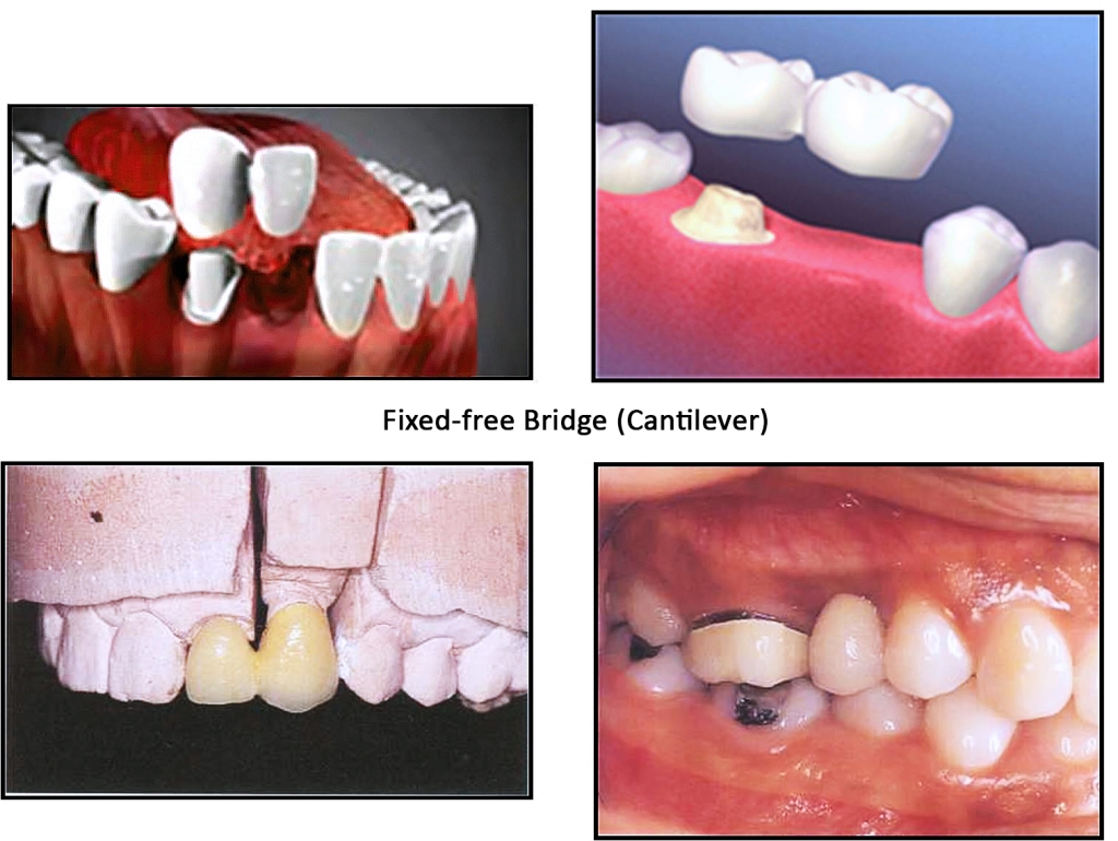
 Each part of the bridge should be designed individually, but within the context of the overall design. The components of a bridge are retainers, pontics and connectors.


